The word vacuum is derived from Latin word “ vacua” meaning empty. According to the definition of American Vacuum Society (1958) the term vacuum refers to a given space filled with gas at a pressure below atmosphere. Whenever air is removed from a closed chamber by any pumping means, a vacuum is obtained. When closed vessel is free of all matters, then perfect or absolute vacuum is achieved. Practically perfect vacuum is not achievable by any means of pumping system. Various degree of vacuum is obtained depending on how much air is removed from the enclosure.
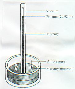
E. Torricelli in his classical work on barometer in 1643 imagined he had produced the perfect vacuum. He filled a long closed tube with mercury and inverted in to a bowl of mercury. The mercury on the tube dropped to a level of about 760 mm height. As no air could enter the space above the column, he thought he had created a space devoid of any substance. What actually remained, as we now know, was mercury vapour and traces of other vapour.
The above experiment showed that atmospheric pressure was capable of supporting a column of mercury in a highly evaluated tube to a height of 760 mm (29.921").
Hence basic unit to express atmospheric pressure is mm/hg or Torr.
So, atmospheric pressure 760 mm/Hg = 760 Torr = 29.921"/Hg = 14.7 PSI.
By any means let us allow very small amount of air or a gas into the space above the mercury column in the tube. The air or gas will exert some pressure on mercury. Therefore the mercury column which was at 760 mm height will now fall slightly to the extent the pressure of air or gas admitted into the top of the tube.
The practical vacuum spectrum here on earth extends from 760 torr down to the lowest pressure so far obtained artificially about 10 –13 to 10 –14 torr. It is convenient to separate this wide vacuum spectrum into ranges.
The most widely accepted classification of vacuum is :
Rough Vacuum : 760 to 1 torr.
Fine Vacuum : 1 to 10 –3 torr.
High Vacuum : 10 (-3) to 10-8 torr.
Ultra High Vacuum (UHV) : 10-8 torr and below.
| Altitude (Feet) | Inches of Hg | mm of Hg |
|---|---|---|
| Sea Level | 29.92 | 760 |
| 500 | 29.38 | 746 |
| 1000 | 28.86 | 733 |
| 1500 | 28.33 | 719 |
| 2000 | 27.82 | 707 |
| 3000 | 26.81 | 681 |
| 4000 | 25.84 | 656 |
| 5000 | 24.84 | 630 |
| 6000 | 23.98 | 609 |
| 7000 | 22.2 | 564 |
| 8000 | 20.6 | 523 |
| 10000 | 14.6 | 370 |
All the pressure units used to express atmospheric pressure are also units of Vacuum.
ATMOSPHEREIC PRESSURE
| 1.013 BAR | 1013 MBAR | 760 mm/Hg (Torr) | 760000 Micron | 14.7 PSI | 29.92 In/Hg | 1.033 Kg/Cm2 | 76 Cm/HG |
ABSOLUTE VACUUM
Commonly used terms are:
Torr, Mbar, mm of Hg, Pascal.
Other terms are:
mm of water, atmosphere, micron etc.
1 mm of Hg = 1 Torr = 1.33 mbar = 1000 micron
1 Atm = 760 torr = 1013 mbar = 1.013 bar
1 micron = 0.001 torr or 0.001 mm of Hg
1 mbar= 0.75 torr
1 torr = 1.33 mbar
1 torr = 1000 micron
Normally in mechanical vacuum gauges atmospheric pressure is shown as zero. In that case perfect vacuum will be -760 torr( - 29.92 “/Hg). Thus if gauge pressure in a vacuum gauge is say – 750 torr, then the vacuum is 10 Torr below the absolute vacuum. Similarly it can be understood for other units also. Conversion of one vacuum unit to another is given in following table.
Following are commonly used conversion table of different units of vacuum.
| Unit | Pa | Bar | mbar | micro bar | Torr (mm/hg) | micron (mTor) | atm | psi | psf |
|---|---|---|---|---|---|---|---|---|---|
| Pa | 1 | 10(-5) | 10(-2) | 10 | 7.5x 10(-3) | 7.5 | 9.87x 10(-6) | 1.45x 10(-4) | 2.09x 10(-2) |
| bar | 10(5) | 1 | 1000 | 10(6) | 750 | 7.5x10(5) | 0.987 | 14.5 | 2.09x 10(3) |
| mbar | 100 | 1x 10(-3) | 1 | 1000 | 0.75 | 750 | 9.87x 10(-4) | 1.45x 10(-2) | 2.09 |
| micro bar | 0.1 | 1x 10(-6) | 1x 10(-3) | 1 | 7.5x 10(-4) | 0.75 | 9.87x 10(-7) | 1.45x 10(-5) | 2.09 x10(-3) |
| Torr | 133 | 1.33x 10(-3) | 1.33 | 1330 | 1 | 1000 | 1.32x 10(-3) | 1.93x 10(-2) | 2.78 |
| micron (mTor) | 0.133 | 1.33x 10(-6) | 1.33x 10(-3) | 1.33 | 1x 10(-3) | 1 | 1.32x 10(-6) | 1.93x 10(-5) | 2.78x 10(-3) |
| atm | 1.01x 10(5) | 1.013 | 1013 | 1.01x 10(6) | 760 | 7.6x 10(5) | 1 | 14.7 | 2.12x 10(3) |
| psi | 6.89x 10(3) | 6.89x 10(-2) | 68.9 | 6.89x 10(4) | 51.71 | 5.17x 10(4) | 6.8x 10(-2) | 1 | 144 |
| psf | 47.8 | 4.78x 10(-4) | 0.478 | 478 | 0.359 | 359 | 4.72x 10(-4) | 6.94x 10(-3) | 1 |
Various types of vacuum gauges are used to measure vacuum. The type of gauge to be used depends on the degree of vacuum available in the system. Following are various types of gauges used to measure vacuum.
| For measuring rough vacuum: | Range |
|---|---|
| Bourdon type dial gauge | 0-760 mm of Hg |
| Liquid Manometer | 0-760 mm of Hg |
| Diaphragm gauge | 0-760 mm of Hg |
| Total pressure gauge (electronic type) | 0-760 mm of Hg |
| For measuring medium & high vacuum: | |
| McLeod gauge | 10-10-3 mm of Hg |
| Capacitance manometer | 100-10-1 mm of Hg |
| Thermocouple | 1-10-3 mm of Hg |
| Pirani | 1000-10-3mm of Hg |
| For measuring Ultra High Vacuum: | |
| Penning, magnetron | 10--3-10-6mm of Hg |
| Ion gauge (cold cathode, hot cathode) | 10-3-10-8mm of Hg |
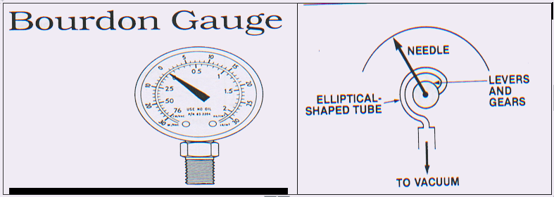
Mechanical vacuum gauges :-
Mechanical gauges are used primarily to give an indication that a vacuum system is actually being pumped down. Since they work on the basis of the force exerted by a gas they will measure the total pressure of a mixture of gases and vapours. There are two types of mechanical gauges.
1) Bourdon gauges where a bourden tube made up of metal, sealed off at one end with other end leading to connection for vacuum system is utilised (see figure)
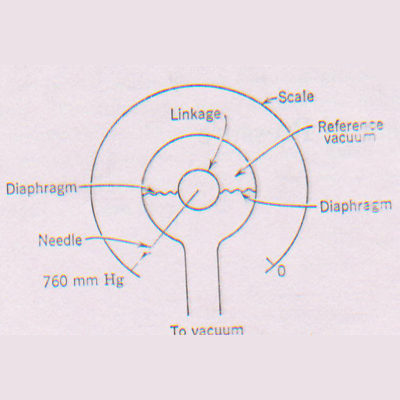
2) A diaphragm gauge usually consists of a flexible metal membrane whose deflection varies with the pressure on the vacuum system.
Hydrostatic Gauges
These measure the actual force exerted by the gas and includes mercury manometer such as open end ‘U’ tube and closed end Mcleod gauge.
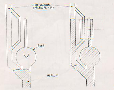
Mcleod gauge utilises Boyle’s Law (Pressure-Volume relation) to determine gas pressure within a system.
The gauge consists of a system of Glass bulb and tubes which are inter connected so that a large volume of gas at pressure P1 is compressed by means of mercury column into a smaller volume of higher pressure P2.The difference in level of mercury (h) between the compressed volume and that at system pressure is a function of pressure in torr.
P1VI=P2V2Where P1, V1 and V2 are know parameters hence P2 which is final pressure can be of trapped gas volumr V calculated and can be expressed in unit of ‘h’. McLeod Gauge is an absolute gauge and is mainly a standard for calibrating other gauges.
Mcleaod gauge does not measure the pressure exerted by water vapor / moisture in the system. Hence reading of Mcleod gauge is the pressure of permanent gas present in the system i.e, vacuum under ideal condition. This is most accurate gauge if there is ideal condition exist in the system.
Thermal Conductivity Gauges
The thermal conductivity of any gas under medium to high vacuum range is proportional to pressure of gas, which has led to the designing of gauges like pirani and thermocouple gauges.
They typically consists of a hot filament mounted in an envelope attached to vacuum system. The temperature of filament depends on heat dissipation due to the gas present in the envelope. At low pressure heat dissipation is less and hence filament temperature is high.
In Pirani gauge one arm of whetstone bridge is a hot filament under vacuum. So temperature variation causes variation in resistance of one arm which is part of bridge circuit that drives the pressure meter. When resistance of one arm changes, the balance of bridge circuit is upset. This unbalance develops a voltage difference at the meter connection which converted into pressure unit normally micron /mbar.
In Thermocouple gauge, a thermocouple of two dissimilar metals is used where hot junction is kept under vacuum.
Temperature of hot junction is a function of pressure in the system. Variation of temperature produces an emf in the thermocuple which is converted into pressure unit normally micron (mbar).
Since the relation between thermal conductivity of gas and temperature of filament holds good at certain range of pressure i.e. between medium to high vacuum range, most of the commercial type pirani / thermocouple gauge operates between 0.5 mbar to 0.001 mbar (375 micron- 0.75 micron).
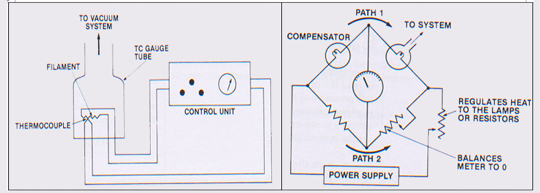
Fig : (a) Principle of thermocouple gauge (b) Arrangement of pirani gauge
The calliberation of above two types of gauges are done by using Mcleod gauge the reference standard.
Ionisation gauge : It works on the principle of measuring electrical currents resulting from ionisation of gas at very low pressure. Gas molecules are ionised by means of electrons emitted by a heated filament. Most of the ionisation gauges operates between high vacuum to ultrahigh vacuum range.
In order to reduce the gas density and thereby gas pressure in the system gas particles must be removed from the volume thereby creating a vacuum. This is the purpose of vacuum pumps. Various types of vacuum pumps are used depending upon the degree of vacuum required to be created. Normally in refrigeration industry rough vacuum and fine vacuum are most commonly used.
| Degree of Vacuum Required | Type of Pump used. |
|---|---|
| Rough vacuum( 760-1 Torr) | Diaphragm pump (oil free) |
| Fine Vacuum (1- 0.001 Torr) | Oil sealed Rotary pump. |
| High Vacuum (10 –3 to 10 –8 Torr) | Diffusion pump/Turbo molecular pump. |
| Ultra High Vacuum ( 10 -8 and above ) | Cryo pump/ Ion pump/ Sublimation pump |
Since the vacuum created by diaphragm pump is not enough to remove moisture from the system, hence the use of diaphragm pump for dehydration of Airconditioning & Refrigeration system is not recommended. Hence oil sealed rotary pump is best suited.
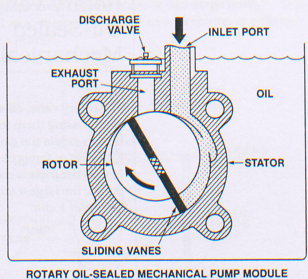
The working principle of oil sealed Rotary pump is shown in figure. The rotor of the pump is fixed eccentrically with respect to stator, leaving a small clearance in between. This small clearance is filled with oil film. The rotor contains spring loaded vane which slides in diametrically opposed slot, thus rotor slides the stator wall all the times. The Gas molecules entering the inlet of the pump, pass in to the crescent shaped volume and is then compressed, forcing the outlet valve open and permitting the gas discharge into the surrounding atmosphere.
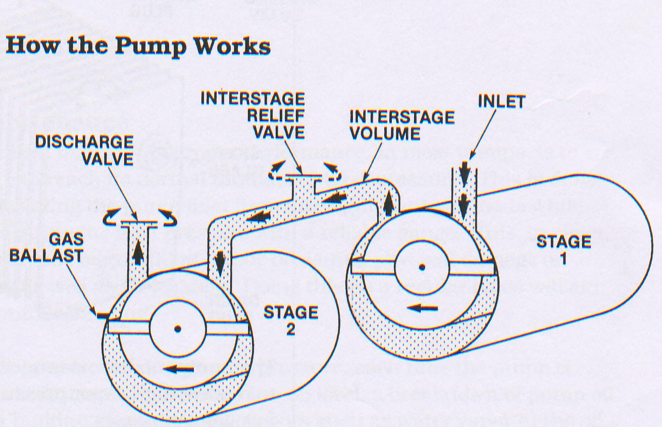
The, ultimate vacuum is limited by back leakage across the top seal, between suction and discharge compartment and to out gassing of lubricating oil. This limitation can be eliminated by designing a two stage vacuum pump where discharge port of 1st stage is fed to suction port of 2nd stage thus resembling two vacuum pumps connected in series. Thus two stage pumps always give better ultimate vacuum than single stage.
Two Stage Vacuum Pumps
Most pumps have two stage to produce better vacuum. A two stage pump is as good as two single stage pump connected in series with each other the exhaust of one pump connected to suction port of other pump. The working mechanism of a two stage vacuum pump is shown in figure
 Two stage vacuum Pump
Air ballast in vacuum pump
The moisture and non-condensable vapour carried into the pump can condense at the compressions side and mix with oil. Such a condition rapidly leads to a deterioration in the performance of pumps. To avoid this, rotary pumps are provided with air ballast. The air ballast is a manually operated valve, which allows a certain amount of atmosphere air into the compression side of the rotor. This air in passing through the passages of the pump body, gets heated up, since the body of the pump obviously get heated while in operation. This hot air picks up lot of moisture from the oil and gets pumped out, thus minimizing the adverse effect of moisture to a great extent.
Needless to point out that when the gas ballast is kept opened, ultimate vacuum drops down but on closing the valve after few minutes, pump pull down is much better.
Oil Back Migration
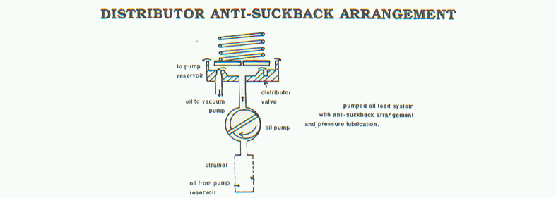
Vacuum pump while running if suddenly stops due to any reason, the oil film formed between rotor and stator deteriorates. Thus the atmospheric air through discharge valve slowly enters into the suction port thus increasing the pressure. If the system is under vacuum, air along with vacuum oil from the pump rush into the system thereby creating a vacuum drop in the system and contaminating the system with vacuum oil. In modern pumps, this difficulties are overcome by providing anti suck- back system. Following mechanisms are normally provided.
- Electrically operated solenoid valve which closes on power failure.
- External non return valve where reverse flow is not possible.
- Built in mechanically operated anti suck back valve. The operation is shown in the figure as under.
Rotary oil sealed pumps are extremely reliable as long as the recommended precautions are taken. For example a small pump can be operated continiously for months without attention, when used on air tight system. On the other hand, pumps used in system which are let down to air again and again or systems which handle large amount of vapour or moisture, requires a fair amount of maintenance. Oil contamination is a common problem. Oil contamination problem can be minimized by using suitable traps such as refrigerated / cold traps to freeze out the vapors, inlet moisture trap with moisture absurbant or by purification of oil through various types of filters or heating the system to eliminate moisture.
In order to enhance the life and performance of vacuum pump, adequate inspection and maintenance schedule includes some or all the following steps.
- Inspect oil level and oil color periodically.
- Check for belt tension in case of belt driven pump.
- Check for over heating of the pump.
- Check for leak in the system connected to vacuum pump.
- Check for filter clogging at the inlet.
- Check for blockage at the outlet nozzle.
In case of any malfunctioning, following trouble shooting chart can be referred for maintenance.
| DEFECTS | POSSIBLE CAUSE | REMEDY |
|---|---|---|
| 1. Pump does not start | - Electrical problem in supply - Direction of motor rotation opposite. - Motor not working - Oil temp blow 12 deg C. - Exhaust filter/line clogged up. - Pump mechanism is jammed. |
- Check electrical installation. - Interchange any tow lead of supply. - Replace motor. - Restore oil above 12 deg C. - Clean exhaust filter - Service pump. |
| 2. Pump does not give desired ultimate vacuum |
- Vacuum gauge not calibrated. - External leakage in the system - Oil is improper. - Inlet lines are clogged. - Anti suck back valve malfunction. - Pump is too small as compared to load. |
- Use correct gauge. - Conduct leak testing to the system. - Replace the oil. - Clean inlet line. - Repair the value. - Use suitable capacity of pump. |
| 3. Pumping speed low. | - Inlet trap is clogged. - Exhaust filter is clogged. - Connecting lines are too narrow. |
- Clean/replace the tarp. - Clean/replace. - Use proper diameter of line. |
| 4. After switch off vacuum drops suddenly to atmosphere . |
- System leak. - Out gasing of material used. - Anti suck back valve malfunction. |
- Conduct leak testing in the system. - Eliminate elastomers used in the system and bake the system to high temp. - Repair/ replace if necessary. |
| 5. Pump get too hot. |
- Improper ventilation at working place. - Process gas too hot. - Oil level low. - Oil nozzle blocked. - Air cooling not proper. - Exhaust filter line blocked. - Oil circulation not proper |
- Improve ventilation. - Use cold trap - Restore oil level. - Clean/replace. - Check cooling fan in the pump. - Clean / replace - Check oil circulation mechanism |
| 6. Oil gets contaminated/ turbid |
- Condensation of vapor - Heavy gas load. - Solvent/ moisture enters into pump. |
- Degas and clean. - Reduce gas load. - Use suitable inlet trap. |
| 7. Pump is excessively noisy. |
- Oil level low. - Silencing nozzle clogged. - Heavy gas load. - Coupling defective. - Vanes & housing damaged. - Shaft key mismatching the key slot |
- Check oil level. - Clean/service. - -Reduce gas low. - Replace coupling. - Repair - Replace shaft key |
A vacuum pump while on regular use need to be checked regularly to ensure best possible performance. For this purpose a high vacuum measuring Mcleod gauge / thermocouple gauge / pirani gauge to be used. A two stage oil sealed rotary vacuum pump is expected to give an ultimate vacuum of around 50 micron at the mouth of pump.
To measure the performance of a vacuum pump, the gauge head ( senser) should be directly attached to the mouth of the pump without any tubing in between. A rubber tubing /charging hose connected between pump and gauge head, exerts an impedance due to out gassing of tube material and its narrow diameter and hence there will be a vacuum loss measured on the gauge.
Following parameters are required to select a suitable pump capacity for particular application :
- PROCESS NAME
- SYSTEM VOLUME
- PROCESS VAPOR LOAD
- NAME OF THE VAPORS.
- PROCESS VAPOR TEMP.
- AIR LEAKAGE RATE OF THE SYSTEM
- PIPING SIZE ( LENGTH & DIA)
- DESIRED ULTIMATE VACUUM
- DESIRED PUMPING CAPACITY.
- UTILITIES AVAILABLE
- EXPECTED INITIAL EVACUATION TIME
- PROCESS CYCLE TIME.
- ELECTRICAL ZONE CLASSIFICATION
REFERENCES
- Andrew Guthrie ( 1965), Vacuum Technology
- Nigel S Harris, Vacuum technology, Edward Vacuum training Centre
- Nigel S Harris Modern Vacuum Practice
- Dr. RA Bellare & Dr. Jayesh Bellare, Vacuum Measurement Manual, second edition-2000